
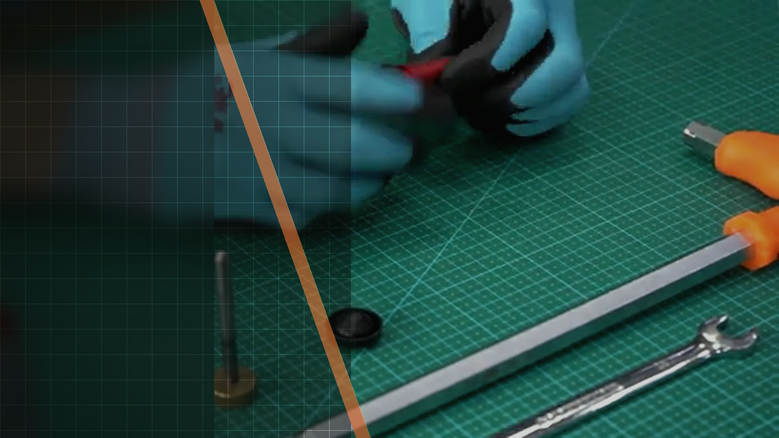
Official Silverback video workshop
Silverback TAC-41 Advanced Hop-Up Kit Installation Guide
This official Silverback video demonstrates how the TAC-41 advanced hop-up kit is fitted, from removing the original wheel and nub to reinstalling the hop-up and inner-barrel assembly. Use this guide when you need to follow the filmed installation sequence and distinguish the low-nub and high-nub adjustment ranges supported by the kit.

01Source-based overview
What this procedure does
The footage begins by removing the screw that retains the hop-up wheel with a 3 mm Allen screwdriver. The original wheel and nub then come out, while the video specifically warns that the feeding mechanism can fall if it is not secured. The reinforced feeder, selected nub and fine-adjustment wheel are subsequently fitted before the hop-up and inner-barrel assembly is reinserted with the feeding mechanism engaged.
The kit is compatible with the TAC-41 AEG hopup SBA-HOP-30 and GBB hopup SBA-HOP-31. Its fine-tuning wheel has a 500 µm amplitude divided into 50 increments of 10 µm, compared with 15 µm increments on the original wheel. With the low nub, the adjustment range is 0 to 500 µm; with the high nub, it is 250 to 750 µm. The reinforced feeder may leave marks on the nozzle without affecting normal operation.
Tools and parts explicitly identified
- 3 mm Allen screwdriver
- original hop-up wheel
- original nub
- reinforced feeder
- low nub
- high nub
- fine-tuning wheel
- ball plunger
- hop-up and inner-barrel assembly
Evidence standard
Every technical statement below is restricted to the official Silverback description, subtitles, on-screen text or visible action. Unstated torque values and compatibility claims are intentionally omitted.
What the footage makes clear
This walkthrough stays close to the official Silverback source. The expanded notes explain what is visible at each checkpoint, while measurements, compatibility and cautions remain limited to what Silverback actually states.
- Installation sequence and visible checkpoints are attributed to the official video visual review observations.
- Compatibility, kit contents, construction details and adjustment specifications are attributed to the official video description.
- No official or automatic English or French subtitle track was available.
| Specification | Source value |
|---|---|
| Compatible AEG hopup | TAC-41 (SBA-HOP-30) |
| Compatible GBB hopup | TAC-41 (SBA-HOP-31) |
| Fine-tuning wheel construction | aviation grade CNC construction with laser marking |
| Reinforced feeder construction | stainless steel CNC construction |
| Low nub construction | stainless steel CNC construction |
| High nub construction | stainless steel CNC construction |
| Fine-tuning wheel amplitude | 500 µm |
| Fine-tuning wheel increments | 50 increments of 10 µm |
| Original wheel increments | 15 µm increments |
| Low nub pressure range | 0 to 500 µm |
| High nub pressure range | 250 to 750 µm |
02Primary source
Watch the official Silverback tutorial
Every technical statement below is restricted to the official Silverback description, subtitles, on-screen text or visible action. Unstated torque values and compatibility claims are intentionally omitted.
03Procedure
Silverback TAC-41 Advanced Hop-Up Kit Installation Guide, step by step


- The feeding mechanism can fall if it is not secured.
- The reinforced feeder may leave some marks on the nozzle without affecting the normal operation of the parts.
- The feeding mechanism is engaged when the hop-up and inner-barrel assembly is reinserted.
- The ball plunger is reinstated.
- The laser marking on the fine-tuning wheel helps return to the exact same click.
04FAQ
TAC-41 tutorial questions
Which TAC-41 hop-up units is the kit compatible with?
The official description lists the TAC-41 AEG-type hopup SBA-HOP-30 and the TAC-41 GBB-type hopup SBA-HOP-31.
What adjustment range does each nub provide?
Used with the low nub, the fine-tuning wheel adjusts rubber pressure from 0 to 500 µm. Used with the high nub, it adjusts rubber pressure from 250 to 750 µm.
How fine is the replacement wheel compared with the original?
The replacement wheel has 50 increments of 10 µm across a 500 µm amplitude, while the original wheel has 15 µm increments. Its laser marking helps return to the exact same click.
Share:
Silverback Advanced Piston Head Installation Guide
Silverback TAC-41 GBB Hopup Rubber Swap Guide