
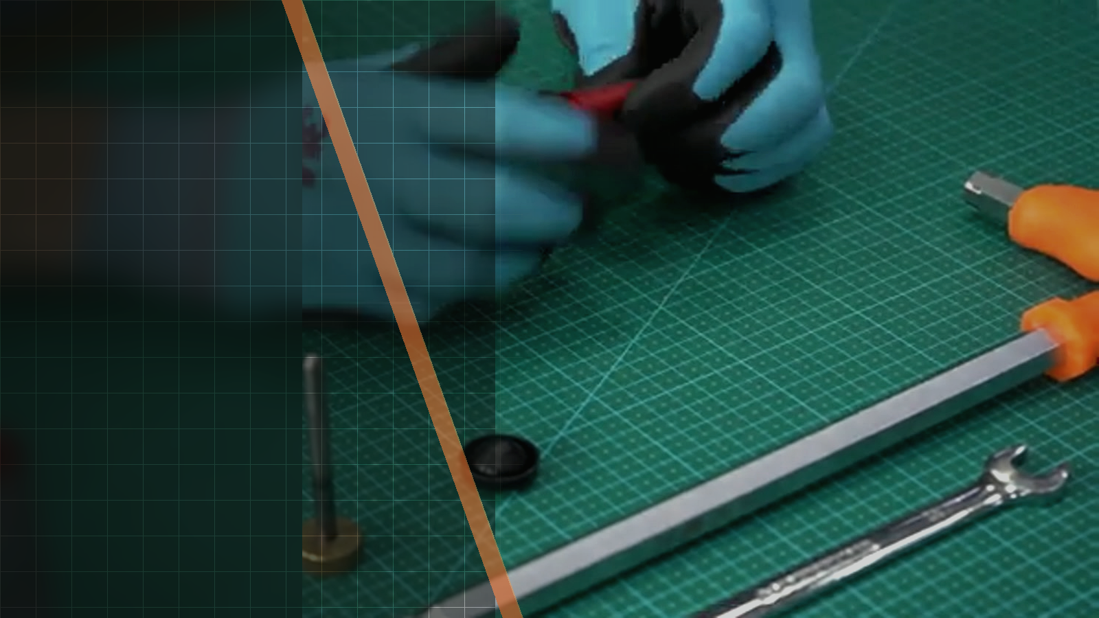
Official Silverback video workshop
Silverback TAC-41 Hopup Rubber Swap Guide
This official Silverback video demonstrates how to swap the hopup rubber in a TAC-41 using an AEG type original hopup. The guide is useful when reviewing the complete visual sequence, from the marked rubber and inner barrel through hop-up disassembly and the final alignment of the chamber, outer barrel and adjustment wheel.

01Source-based overview
What this procedure does
The video begins with the parts and tools arranged for the hopup rubber swap: PTFE tape, a marker, the AEG hop rubber, a 2.5 mm Allen tool, inner barrel, O-ring, M3x6 screws and the hop-up chamber. The rubber and barrel carry alignment marks. During this part of the sequence, a 6.00 mm pin may be inserted in the barrel while the M3x6 screws are tightened; the component visible through the chamber is identified as the hop-up feeder, not the barrel.
The later footage shows further disassembly involving the guide rod, outer barrel, spacers/muzzle, hop-up parts and a 3 mm Allen tool. Reassembly shows a lubricated assembly inserted with its arrow upward and aligned to the barrel axis, followed by alignment of the chamber with the outer barrel. The adjustment wheel is set between 0 and 1 before its screw is tightened. Silverback states that changing the rubber may affect muzzle energy and that users must obey the laws governing airsoft-gun ownership in their country.
Tools and parts explicitly identified
- PTFE tape
- marker
- AEG hop rubber
- 2.5 mm Allen tool
- inner barrel
- O-ring
- M3x6 screws
- hop-up chamber
- 6.00 mm pin
- guide rod
- outer barrel
- spacers/muzzle
- hop-up parts
- 3 mm Allen tool
Evidence standard
Every technical statement below is restricted to the official Silverback description, subtitles, on-screen text or visible action. Unstated torque values and compatibility claims are intentionally omitted.
What the footage makes clear
This walkthrough stays close to the official Silverback source. The expanded notes explain what is visible at each checkpoint, while measurements, compatibility and cautions remain limited to what Silverback actually states.
- The official video title and description establish the TAC-41 AEG hopup-rubber-swap subject and the AEG type original hopup.
- The visual review observations establish the opening layout, alignment marks, pin, chamber identification, disassembly parts, reassembly arrow and adjustment-wheel position.
- The official description supplies the muzzle-energy and local-law cautions.
- The fixed timestamps establish the five chronological frame checkpoints.
| Specification | Source value |
|---|---|
| Platform | tac-41 |
| Hopup rubber | AEG type original hopup |
| Video duration | 306 |
02Primary source
Watch the official Silverback tutorial
Every technical statement below is restricted to the official Silverback description, subtitles, on-screen text or visible action. Unstated torque values and compatibility claims are intentionally omitted.
03Procedure
Silverback TAC-41 Hopup Rubber Swap Guide, step by step


- Changing the hopup rubber will affect the muzzle energy of the airsoft gun.
- Users should obey the laws regarding ownership of airsoft guns in their country.
- The rubber and inner barrel alignment marks correspond.
- The reassembled assembly arrow points upward and the assembly is aligned to the barrel axis.
- The chamber is aligned with the outer barrel.
- The adjustment wheel is set between 0 and 1 before its screw is tightened.
04FAQ
TAC-41 tutorial questions
What type of hopup rubber does the official video cover?
It covers swapping the hopup rubber using an AEG type original hopup on TAC-41.
What is the component visible through the chamber?
The visual review identifies it as the hop-up feeder rather than the barrel.
What effect does Silverback associate with changing the hopup rubber?
The official description states that changing the hopup rubber will affect the muzzle energy of the airsoft gun.
Share:
Silverback TAC-41 P Stock Ergonomics Guide
Silverback TAC-41 Trigger Adjustment Guide